Home › Forums › Maintenance of Grummans › Electrical › Fuses to Circuit Breakers
- This topic has 6 replies, 1 voice, and was last updated 3 years, 11 months ago by
 Richard Harrison.
-
AuthorPosts
-
-
June 1, 2020 at 21:38 #14079
 Richard HarrisonParticipant
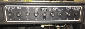
I started the annual on my ’76 AA-1B, and I decided to do some panel work this time. Last year I had replaced all the legacy CB’s with Klixon breakers on my Cessna 182, and my ’69 Yankee project also has Klixon breakers. So it is time to do the same to my AA-1B. I got the panel stripped down today (removed the overlay, the vent airbox, glove box, etc). Getting the old fuse holders out is a chore. They were all soldered up from the back but install from the front. The only way to get them out is to break the front off. See attached pictures of the start of this project.
I also will be installing a new intercom (my old portable intercom that sat in the tray between the seats died after only 25 years), and a fuel flow gage.
I will update pictures as I go.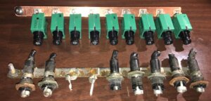


Attachments:
You must be logged in to view attached files. -
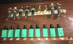
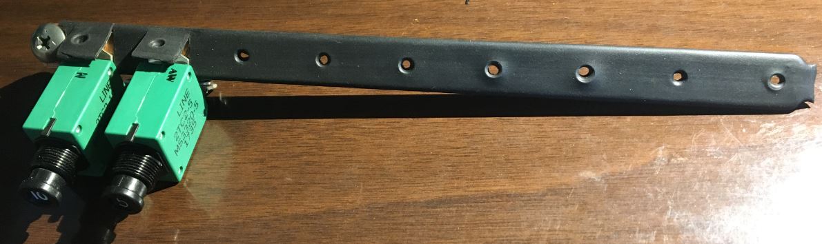
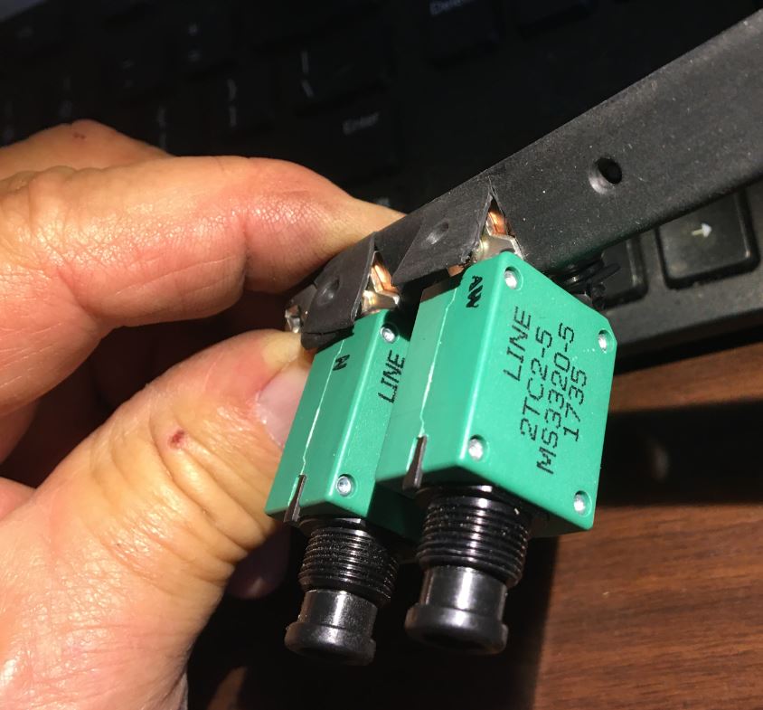
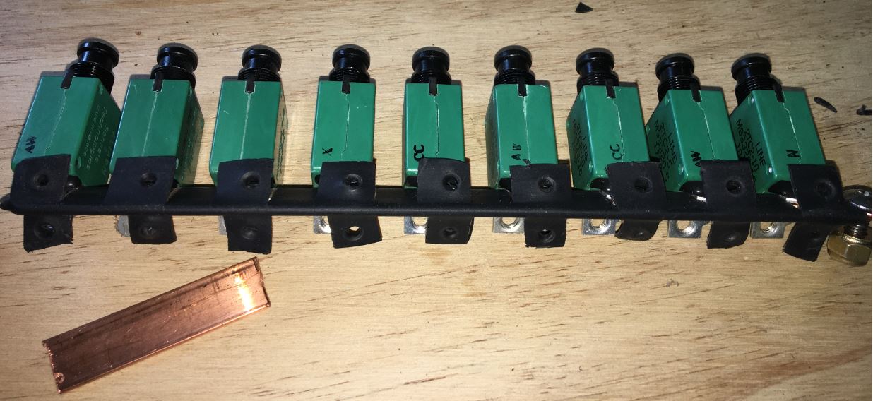
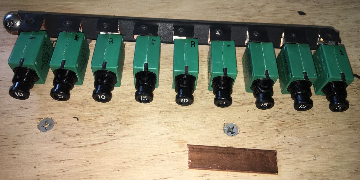
June 4, 2020 at 19:19 #14101Richard HarrisonParticipant More on this. Got the old breakers and fuse holders out. I made a new buss out of 1/2″ wide .0625″ (1/16″) thick copper strip. The spacing between the fuses is 7/8″. I got it assembled with the breakers and did a trial fit. I am using the Klixon model 2TC2 breakers.
Attachments:
You must be logged in to view attached files. -
June 4, 2020 at 20:36 #14105Richard HarrisonParticipant
About a week ago I was talking to Roscoe about replacing the fuses and CBs, he brought up something he had done in the past was putting Heat Shrink over the buss bar and notching it for where the new CBs attach. This is to help protect it from wayward debris contact with the buss.
Well, when I was removing the old fuse buss a small allen wrench fell out. It had burn marks on it. Know idea how long it has been there, but I remember a few years back my 60A breaker popped once and I never did figure out why. Now I suspect I know the reason. Being this area is tightly sandwiched between the glove box and the air vent box, it is very difficult to access.
So I decided to give Roscoe’s suggestion a try. Here is my results to date. I am cutting flaps in the shrink boot to allow the mating surface of the breaker and the screw to contact the copper buss.Attachments:
You must be logged in to view attached files. -
June 5, 2020 at 14:07 #14119Richard HarrisonParticipant
-
June 5, 2020 at 18:36 #14125Richard HarrisonParticipant
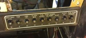
OK, final installment for this piece. Got the breakers installed in the panel, crimped new ring terminals on all the wires and connected. On the AA-1B & C the panel fuse position marked “Fuel Gauges” is not used (but there was a wire connected to it going into the harness), so it will be used for the Aux Power outlet (Cigar Liter).
Now on to the other projects…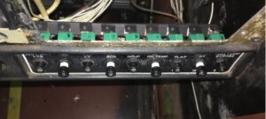
Attachments:
You must be logged in to view attached files. -
June 6, 2020 at 19:16 #14137Richard HarrisonParticipant
On a related note I got my next order of .5″ X .0625″ X 12″ copper bus material in so now I can replace the Avionics bus. I pulled out the factory bus and fuses. Just like my Cessna 182, the bus was made from .032 aluminium (looks like pieces made out of the scrap aluminum pile). At least the fuse bus was made from .032 copper.
Attachments:
You must be logged in to view attached files. -
June 6, 2020 at 21:22 #14139Richard HarrisonParticipant
To add one more note to this, the spacing of the fuses on the right of the panel is 0.875″. The spacing of the circuit breakers is 0.8″. This is on the later panel (9 fuse and 8 circuit breaker positions). Not sure if this is the same for the early panels
-
-
AuthorPosts


- You must be logged in to reply to this topic.