Home › Forums › Maintenance of Grummans › Electrical › Fuse Replacement with Breakers
Tagged: breakers, Circuit Breakers, Electrical Load, Fuse, Fuse Circuits, fuse replacement, panel redo
- This topic has 1 reply, 2 voices, and was last updated 8 years, 10 months ago by
 Tracy Norris.
-
AuthorPosts
-
-
May 27, 2015 at 21:08 #1725
 Roscoe RoschéKeymaster
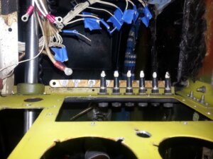
We have 9 fuses on the lower right panel. (2) 10 Amp, (4) 5 amp, (3) 15 amp, which cover as follows (left to right):
Instrument – Nav Lights: 10
T&B: 5
Landing Light: 10
Flashing Beacon: 15
Fuel Gages: 5
Stall Warning, Oil Temp: 5
Flap: 15
Pitot Heat: 15
Fuel Pump, Strobes: 5These are being replaced with the Klixon 7277 Series Breakers. Part numbers for Klixon breakers follows the convention: SSSS-P-A, where
SSS is the series (in our case 7277)
P – is the length of the pull knob/reset button
A – amp rating of the breaker (1/2 to 15)So we order the 7277-2-A breakers same as the fuses except for the Flashing beacon, it was replaced with a combined nav light/ led strobe, that draws a max of 0.93 amps, so we ordered a 7277-2-2 breaker for that slot.
Here is how we are doing/did it (not quite complete). With the work space clear we first removed the battery.
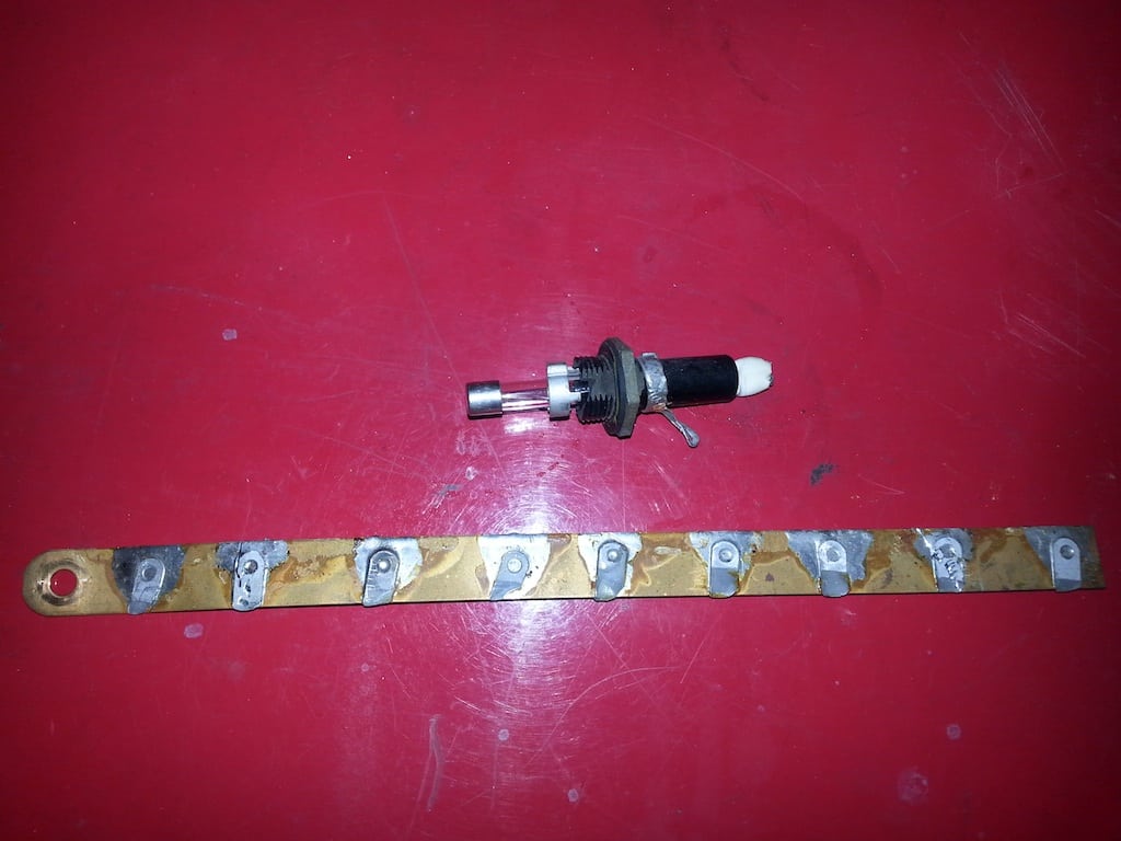
Next with the removal of the overlay, the gauges (Mitchell), the glove box, and naca air box. Now that we had working room, we cut the wires closet to the fuse for all nine. These fuses have the other tab soldered to a bus bar made of copper. You can try and get a torch or a hot, big iron in there, but this works well too. Take a pair of pliers and grab the outside of the fuse near the labels, hold the locking nut on the inside with a wrench. As you twist in a counter-clockwise direction, you will loosen the nut and peel the tab off the solders. This worked on eight of the fuses.
One, was heat damaged and about to fail, but most of the time this works easily. Then the bus was removed from the #2 main bus cables (the jumper from the left side and the one from the amp-meter).
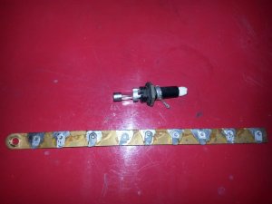
Now drill the bus bar on the same spacing using the solder tab imprints to drill a 9/64 inch hold (for the #6 machine screw on the breaker). Now attach breakers and then the bus. Here is what that looks like back in place.
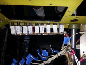
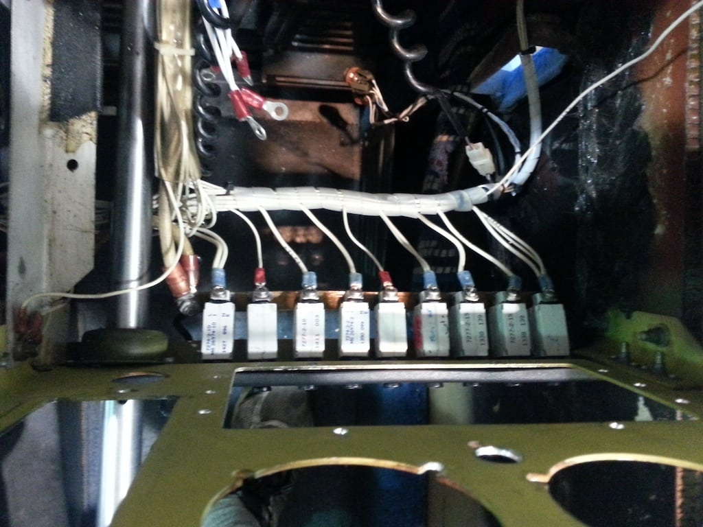
Now connect the wires you cut, crimping eyelets on the wire/wires to attach to the other pole of the breakers. Finally attach the bus. Then you can push them through the panel and add the locking nuts and washer.
Pretty right?

Now spi-wrap the wire bundles to make it nice and clean.

-
July 1, 2015 at 11:38 #1795
 Tracy NorrisParticipant
Nice work Roscoe!
-
-
AuthorPosts


- You must be logged in to reply to this topic.